


 English
 한국어
 русский

Address:
No.233-3 Yangchenghu Road, Xixiashu Industrial Park, Xinbei District, Changzhou City, Jiangsu Province


Content
Every machinist eventually reaches the same moment: the part is clamped, the tool is in the holder, and the only thing left to decide is how fast to run. Cutting speed calculation is what turns that guess into a number you can defend. The arithmetic is short, but a misplaced unit or the wrong diameter can put you off by a factor of ten.
We make solid carbide end mills in Changzhou for shops cutting aluminum, stainless steel, titanium, graphite and hardened steel, and the same questions come up in almost every conversation about parameters. This guide is the answer we usually give: the formulas, a handful of worked examples, and the practical corrections that turn a catalog value into a cut that sounds right.
Cutting speed, normally written Vc, is the rate at which the workpiece surface travels past the cutting edge. It belongs to the material pair and the cutting conditions, not to the spindle. Aluminum might run at 300 m/min, a 304 stainless part at 60 m/min, and a 50 HRC insert at around 90 m/min with the right coating and a rigid setup.
Spindle speed is a consequence of cutting speed and tool diameter. Because the formula divides by diameter, a 3 mm cutter has to spin more than six times faster than a 20 mm cutter to reach the same Vc. That single relationship explains most of the confusion in a shop where one program is reused with a different tool.
In metric units, cutting speed relates to diameter and spindle speed like this: Vc (m/min) = 3.1416 x D (mm) x n (rpm) / 1000. The 1000 converts millimeters into meters. Rearranged for the number you actually dial in, it becomes n (rpm) = 1000 x Vc / (3.1416 x D).
In imperial units the constant changes. Vc is expressed in surface feet per minute and diameter in inches, giving n = 3.82 x SFM / D, where 3.82 is simply 12 divided by 3.1416. The table below collects the three relationships you will use most.
| Quantity | Metric formula | Imperial formula |
|---|---|---|
| Cutting speed Vc | Vc = 3.1416 x D x n / 1000 | Vc = 3.1416 x D x n / 12 |
| Spindle speed n | n = 1000 x Vc / (3.1416 x D) | n = 3.82 x Vc / D |
| Feed per minute vf | vf = fz x z x n | vf = fz x z x n |
A quick sanity check before you press cycle start: 100 m/min on a 10 mm cutter should return roughly 3,180 rpm. If your answer comes out as 318 or 31,800, a unit has slipped somewhere and the rest of the program is built on sand.
Numbers are easier to trust when you can see where they came from. The following values assume a 10 mm solid carbide end mill, around 50 percent radial engagement, flood coolant and a rigid 40-taper machine. They are starting points, not laws of nature.
| Material | Vc (m/min) | Spindle speed (rpm) | fz (mm/tooth) | Flutes | Feed (mm/min) |
|---|---|---|---|---|---|
| Aluminum 6061 | 300 | 9,550 | 0.05 | 3 | 1,432 |
| Mild steel 1018 | 120 | 3,820 | 0.04 | 4 | 611 |
| Stainless 304 | 60 | 1,910 | 0.03 | 4 | 229 |
| Titanium Ti-6Al-4V | 45 | 1,432 | 0.03 | 4 | 172 |
| Hardened steel 50 HRC | 90 | 2,865 | 0.02 | 4 | 229 |
For general purpose work in mild and alloy steel, a 4-flute flat end mill is the usual starting point: enough core strength to survive the feed, and enough chip room to clear the cut.
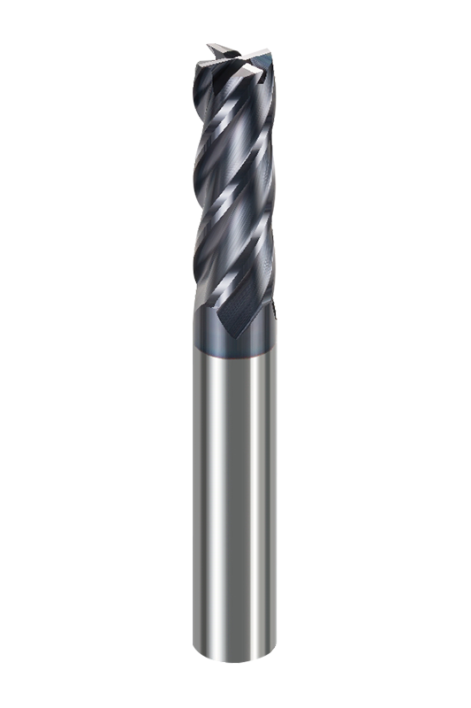 NNC 4-Flute Flat End Mills for General MillingUniversal carbide cutters in diameters from 1 to 20 mm, suited to mild and alloy steel as well as broader material groups.View Product →
If the machine cannot reach the calculated rpm, keep the feed per tooth and accept the lower surface speed instead of raising fz to compensate. A tool that is under-spun but properly fed usually outlasts one that is over-fed to make up for a slow spindle.
Spindle speed alone does not make a chip. Feed rate ties the rotation to the tooth load: vf = n x fz x z, where fz is feed per tooth and z the flute count. Feed per revolution, useful when comparing with tapping or drilling data, is simply fz x z. Using the aluminum example above, 9,550 rpm with 3 flutes at 0.05 mm per tooth gives about 1,432 mm/min.
Chip load is the other half of the calculation. If fz is too small relative to the edge radius, the tool rubs instead of cutting, work hardening climbs and the edge wears on its flank. If fz is too large for the core diameter, the tool deflects and the finish goes with it. The window between the two is narrower on small cutters, which is why micro tools deserve their own numbers rather than a scaled copy of a 12 mm program.
When radial engagement drops below roughly half the cutter diameter, the real chip is thinner than the programmed fz. Feed per tooth can then be raised to keep the edge in a proper cut. This is where a calculated feed rate becomes a starting point rather than a final answer.
We keep a broader reference of calculated values and material notes in our milling cutting speeds chart with RPM and feed rates, which is useful when you need a second opinion on a familiar material.
Two cutters of the same diameter can carry very different feeds. Flute count changes chip room, coating changes heat resistance, and the substrate decides how much edge wear the tool will tolerate. A 2-flute cutter wins in aluminum because the chip has somewhere to go; a 6-flute cutter wins in hardened steel because the load is spread across more edges.
Stainless rewards a moderate cutting speed and a firm feed. Unequal flute spacing helps suppress chatter, which in turn lets you stay closer to the calculated values instead of backing off. A dedicated tool makes this easier than a general purpose cutter pushed outside its comfort zone.
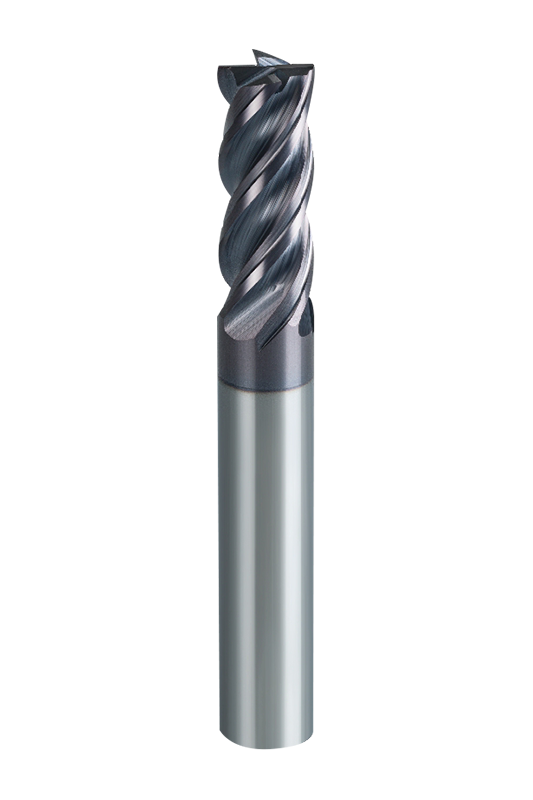 NNB 4-Flute Unequal Pitch End Mill for Stainless SteelDedicated solid carbide cutter with unequal flute spacing to limit chatter, available in 4–20 mm diameters for stainless and related steels.View Product →
Titanium sits at the low end of the cutting speed range for a good reason: heat stays in the edge rather than leaving with the chip. Keep Vc conservative, keep the feed high enough to avoid rubbing, and use plenty of coolant.
 NNT 4-Flute Flat End Mills for Titanium AlloyVariable helix and unequal division with large chip space, offered in 6–20 mm diameters for titanium machining and roughing.View Product →
Aluminum tolerates cutting speeds that would destroy a steel cutter, so the limit is usually the spindle, not the tool. Hardened steel is the opposite: high speeds are possible with the right coating, but only if the machine is rigid and the runout is small, because a hard material forgives nothing at the edge.
Cutting speed calculation is really a conversation between the material, the tool and the machine. Get the units right, respect the diameter, and treat every result as a starting point that the first cut will refine. If you would like a second opinion on parameters for a specific job, our engineers are glad to look at the drawing and the setup with you, and you can browse our solid carbide end mill range to see which geometry fits the material you are cutting.

We are End Mills Manufacturer and End Mill Bits Factory. Our Footprints Are Around The World, We provide quality products and services to customers from all over the world.


No.233-3 Yangchenghu Road, Xixiashu Industrial Park, Xinbei District, Changzhou City, Jiangsu Province


+86-18068566610


sales@magotan-tools.com
+86-18068566610
