
Address:
No.233-3 Yangchenghu Road, Xixiashu Industrial Park, Xinbei District, Changzhou City, Jiangsu Province


Content
You load a fresh piece of 316 stainless steel onto your CNC mill, program a 0.500" depth of cut, and your 1/4" 4-flute end mill snaps on the first pass. The material isn't the problem. The machine isn't out of alignment. The real culprit is a mismatched set of dimensions — a flute length too long for the cut, a diameter too small for the forces involved, and a flute count that can't evacuate chips. End mill dimensions aren't just numbers on a spec sheet; they are the difference between a flawless finish and a pile of broken tools.
Every decision you make — from shank diameter to overall length — directly controls tool rigidity, chip evacuation, and surface finish. Whether you are slotting aluminum at high speed or taking a finishing pass on hardened steel, matching the physical dimensions to the operation is non-negotiable. This reference breaks down the key dimensional standards, material-specific sizing rules, and tolerance classes that professional machinists rely on every day.
End mills follow a core set of dimensional parameters: cutting diameter, flute length, shank diameter, and overall length. In most catalog systems, these are paired and interdependent. A diameter of 6 mm typically comes with a 6 mm shank, a flute length of 13–15 mm, and an overall length between 50 mm and 57 mm, though long-series and stub versions diverge from those norms.
The most frequently used sizes — 1/4" and 6 mm — dominate general-purpose machining because they balance rigidity and chip clearance. Here are the standard inch and metric dimensions you'll encounter in high‑performance solid carbide tools.
| Cutting Diameter (in) | Flute Length (in) | Shank Diameter (in) | Overall Length (in) |
|---|---|---|---|
| 1/8 | 1/4 | 1/8 | 1-1/2 |
| 3/16 | 3/8 | 3/16 | 2 |
| 1/4 | 1/2 | 1/4 | 2-1/2 |
| 5/16 | 5/8 | 5/16 | 2-1/2 |
| 3/8 | 3/4 | 3/8 | 2-1/2 |
| 1/2 | 1 | 1/2 | 3 |
| 5/8 | 1-1/4 | 5/8 | 3-1/2 |
| 3/4 | 1-1/2 | 3/4 | 4 |
| 1 | 2 | 1 | 4-1/2 |
| Cutting Diameter (mm) | Flute Length (mm) | Shank Diameter (mm) | Overall Length (mm) |
|---|---|---|---|
| 2 | 6 | 4 | 38 |
| 3 | 8 | 3 | 38 |
| 4 | 11 | 4 | 50 |
| 5 | 13 | 5 | 50 |
| 6 | 15 | 6 | 57 |
| 8 | 20 | 8 | 63 |
| 10 | 25 | 10 | 72 |
| 12 | 30 | 12 | 83 |
| 16 | 40 | 16 | 92 |
| 20 | 45 | 20 | 104 |
| 25 | 55 | 25 | 121 |
These values represent standard "regular length" tools. Stub length end mills reduce flute length by about 30–40 %, delivering far higher rigidity for aggressive roughing, while long-reach variants extend flute length to 5× diameter or more — an option that demands reduced radial engagement and careful runout control.
Machinists working with stainless steel often reach for a 6 mm or 1/2" diameter as a starting point because it provides enough cross-sectional strength for side milling while still allowing slotting with manageable deflection. The next section explains why flute count changes the effective working dimensions.
The number of flutes doesn't change the labeled dimensions, but it dramatically alters how the tool behaves inside a given diameter. A 4-flute 6 mm end mill has a larger core diameter than its 2-flute counterpart — the space between flutes shrinks, which boosts rigidity but reduces chip evacuation volume. This trade-off defines which operations a specific size can handle safely.
When the operation is a full-width slot, a 2-flute end mill with a diameter at least twice the depth of cut generally outperforms a 4-flute cutter of the same diameter because it can transport chips out of the cut zone. In contrast, for profiling passes under 20 % radial engagement, a 4-flute tool with a flute length kept to 3× diameter or less yields the best wall finish and longest tool life.
Titanium, stainless steel, and nickel-based alloys punish tools that are either too slender or too aggressive in flute length. The root problem is vibration. As flute length grows beyond 3× the cutting diameter, harmonic deflection accelerates fatigue failure, regardless of coating. For these materials, the safe operating window shrinks significantly.
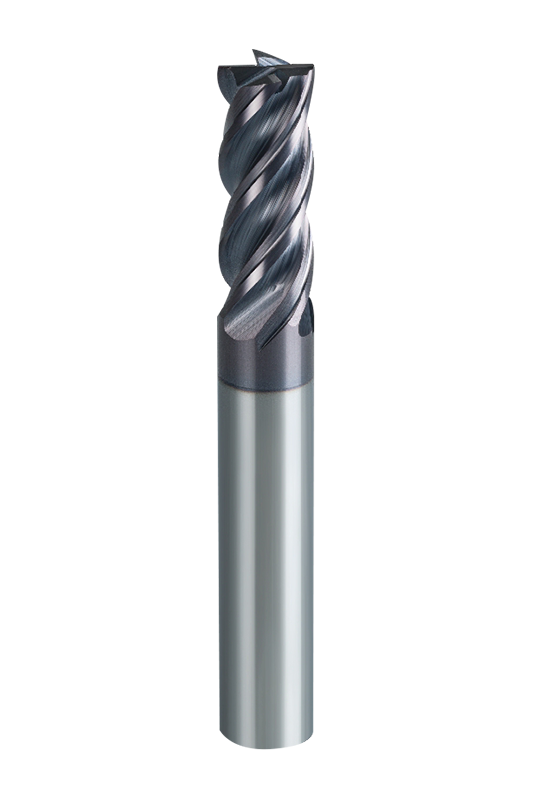
When machining stainless steel, a diameter range of 6 mm to 12 mm (1/4" to 1/2") consistently delivers the best combination of stability and metal removal rate. Below 6 mm, the risk of catastrophic breakage rises, particularly in slotting, while diameters above 12 mm can generate excessive cutting forces that challenge lower-horsepower spindles. A flute length no greater than 3× the diameter is the single most effective rule for preventing chatter. Choosing an unequal tooth pitch design further disrupts harmonic buildup. Our solid carbide end mills for stainless steel illustrate this dimensional logic, pairing optimized flute geometry with precise run‑out control.
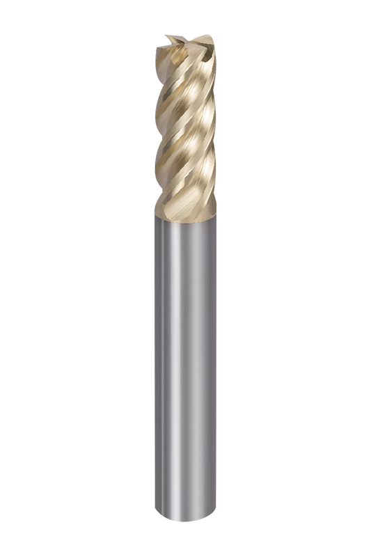
For titanium alloys, the guidelines narrow even further. Stick to diameters between 6 mm and 10 mm and insist on a flute length no more than 2.5× the diameter. Because titanium’s low thermal conductivity concentrates heat at the cutting edge, a shorter flute length reduces time in the cut and helps thin‑out chip thickness, lowering the heat load per pass. This strategy is embedded in tools like the dedicated carbide end mills for titanium, whose dimensions are configured for high‑pressure coolant delivery and low‑deflection cuts.
In both scenarios, the shank diameter should match the cutting diameter wherever possible to maximize stiffness. A necked-down end mill should only be used when reach requirements leave no alternative, and then the neck diameter must be at least 70 % of the cutting diameter to avoid a weak mechanical junction.
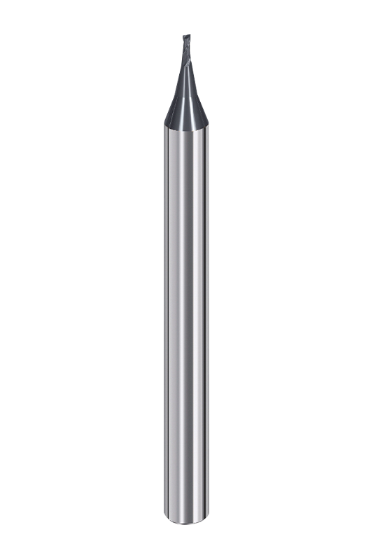
Below 3 mm in diameter, end mill dimensions shift away from rigid rules toward a more intricate balance of fragility and chip evacuation. Micro end mills — typically spanning 0.5 mm to 3 mm — are used for electrode machining, medical device components, and micro‑fluidics. At these scales, even 0.003 mm of runout can snap a tool.
The majority of micro end mills feature a shank diameter of 3 mm or 4 mm, regardless of the cutting diameter. This provides a consistent clamping surface for high‑precision tool holders, while the flute length rarely exceeds 2.5× the diameter to keep the slender neck as short as possible. A 1 mm four‑flute ball nose end mill, for example, might have a flute length of 2 mm and an overall length of 38 mm, allowing it to reach small cavities without buckling.
| Cutting Diameter (mm) | Flute Length (mm) | Shank Diameter (mm) | Overall Length (mm) | RPM Range | Feed Rate (mm/min) |
|---|---|---|---|---|---|
| 0.5 | 1 | 4 | 38 | 40,000 – 60,000 | 200 – 400 |
| 1.0 | 2 | 4 | 38 | 40,000 – 50,000 | 300 – 600 |
| 1.5 | 3 | 4 | 38 | 30,000 – 40,000 | 400 – 800 |
| 2.0 | 4 | 4 | 50 | 25,000 – 35,000 | 500 – 1,000 |
| 3.0 | 6 | 4 | 50 | 20,000 – 30,000 | 600 – 1,200 |
Precision in these dimensions is non‑negotiable. Tool holders with runout under 3 µm and balanced collets are mandatory. When exploring extreme micro sizes, many shops turn to high‑precision end mills engineered for graphite or electrode work, where even a whisper of dimensional error becomes visible on the finished part. The ultra-hard carbide end mill range provides an example of how tight dimensional control can extend tool life at the micro scale.
End mill dimensions aren't just about the numbers themselves — they carry a tolerance grade that determines how faithfully the shank sits in the holder. The most common shank tolerance classes for solid carbide tools are h6 and h7, defined by ISO 286. A h6 shank with a nominal diameter of 6 mm will measure between 5.992 mm and 6.000 mm, yielding a maximum clearance of only 8 µm. An h7 shank adds twice that tolerance.
In practical terms, a h6 shank reduces radial runout to under 5 µm when paired with a high‑quality collet or hydraulic chuck, which directly improves surface finish and prevents one flute from bearing a disproportionate chip load. This is why precision finishing operations for mold and die work almost always specify h6 shanks. An h7 shank, while more economical, is better suited to roughing operations where absolute concentricity is less critical.
| Tolerance Class | Shank Diameter Range (mm) | Allowable Deviation (µm) | Typical Application |
|---|---|---|---|
| h5 | 1 – 6 | 0 / –5 | Ultra‑precision micro machining |
| h6 | 1 – 25 | 0 / –8 (for ≤6 mm) | Precision finishing, hardened steel |
| h7 | 3 – 25 | 0 / –15 (for ≤6 mm) | General roughing, non‑critical profiling |
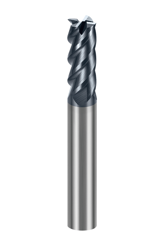
When selecting end mill dimensions, verifying the tolerance class is just as important as confirming the diameter. A 6 mm h6 end mill from a high‑precision series will outperform a generic 6 mm h7 tool at every pass where wall finish or profile accuracy matters. Shops targeting Ra 0.4 µm or finer on hardened steel often rely on tools like the high‑precision 4‑flute flat end mills, whose dimensional consistency supports exacting mold geometries.
Stock dimensions cover roughly 80 % of machining jobs. But when you need a specific reach, a necked profile, an odd diameter such as 7.3 mm or a 0.265" cutting edge, you leave the catalog behind and enter custom territory. Fortunately, short‑run custom end mills have become accessible without requiring massive order volumes.
Ordering a non‑standard end mill requires providing five critical dimensions plus operation parameters. Typical minimum order quantities (MOQ) start as low as 5 pieces, with lead times ranging from 2 to 3 weeks, depending on coating complexity and blank availability. To initiate a custom request, you will need to deliver the following specifications:
Engaging with an engineering team early in this process will surface dimensional limits. For instance, a neck diameter below 60 % of the cutting diameter creates a fracture risk so high that the tool becomes impractical. When in doubt, lean toward a slightly thicker neck and a shorter flute. Tight communication up front prevents scrap later.
Translating workpiece requirements into a specific set of dimensions can be distilled into a simple table. The matrix below couples material type, depth of cut, and machine rigidity with a recommended starting diameter, flute count, and maximum safe flute length. Use it as a rough cut — fine‑tune with your actual setup data.
| Workpiece Material | Max Depth of Cut (Ap) | Machine Rigidity | Recommended Diameter | Flute Count | Max Flute Length |
|---|---|---|---|---|---|
| Aluminum (6061, 7075) | < 0.5 × D | Medium – High | 6 – 12 mm | 2 – 3 | 4 × D |
| Stainless (304, 316) | < 0.3 × D | High | 6 – 12 mm | 4 | 3 × D |
| Titanium (Ti‑6Al‑4V) | < 0.25 × D | High | 6 – 10 mm | 4 | 2.5 × D |
| Hardened steel (52‑60 HRC) | < 0.1 × D | Very High | 4 – 8 mm | 4 – 6 | 2 × D |
| Graphite | < 0.5 × D | Medium | 1 – 8 mm | 2 (ball) | 3 × D |
| Inconel 718 | < 0.2 × D | Very High | 6 – 10 mm | 4 | 2.5 × D |
A stiff machining center and careful chip thinning strategy can stretch these limits by 10–15 %, but exceeding the recommended flute length without reducing the radial engagement will almost always end in tool failure. This matrix reinforces the central point: dimensions are not one‑size‑fits‑all; they must be tuned to the material and the machine.
Every dimension on an end mill influences a physical outcome — rigidity, chip clearance, heat dissipation, or clamping precision. When you distill decades of tool engineering into a handful of actionable rules, the following patterns emerge:
When in doubt, start with a 6 mm or 1/4" four‑flute tool with regular length. It is the most tested dimension in the machining world, and it will tell you within two cuts whether you need a longer reach, a smaller diameter, or a different flute count.
We are End Mills Manufacturer and End Mill Bits Factory. Our Footprints Are Around The World, We provide quality products and services to customers from all over the world.

No.233-3 Yangchenghu Road, Xixiashu Industrial Park, Xinbei District, Changzhou City, Jiangsu Province

+86-18068566610

sales@magotan-tools.com
+86-18068566610
