
Address:
No.233-3 Yangchenghu Road, Xixiashu Industrial Park, Xinbei District, Changzhou City, Jiangsu Province


Content
A single chipped edge on a finishing end mill can turn a precision mold cavity into scrap in seconds. End mill machining is the process of removing material with a rotating cutter that cuts with both its end face and its peripheral edges. Unlike a drill that advances axially to create a hole, an end mill moves laterally, plunges, or ramps to generate complex profiles, slots, pockets, and 3D contours.
The distinction between end milling and face milling matters for tool selection and strategy. Face mills cut predominantly with the periphery at shallow axial depths, while end mills can handle substantial axial engagement and side milling simultaneously. A drill relies only on its chisel edge and lips; an end mill distributes cutting forces across multiple flutes and uses helix angles to control chip evacuation.
In practice, this multi‑axis capability makes end milling the backbone of CNC production. Whether it’s roughing a steel fixture plate, semi‑finishing a titanium aircraft bracket, or finishing a graphite electrode, the end mill’s versatility drives the decision.
Choosing the wrong end mill geometry forces the operator into a corner—poor chip evacuation, chatter, and accelerated wear. The industry standardizes end mills into three main tip geometries: flat (square), ball nose, and corner radius (bull nose). Flute count then determines how each geometry behaves under different chip loads and material conditions.
| Type | Geometry Feature | Best Application | Recommended Materials |
|---|---|---|---|
| Flat end mill | Sharp 90° corner | Square shoulder slots, profiling, roughing flat surfaces | Steel, stainless, cast iron, aluminum |
| Ball nose end mill | Hemispherical tip | 3D contour finishing, die/mold cavities, sculpted surfaces | Hardened steel, graphite, titanium (finishing) |
| Corner radius end mill | Blended radius on corners | Shoulder milling with stress relief, roughing transitions | High-temp alloys, stainless, titanium, hardened steels |
| 2‑flute end mill | Large flute gullets | Slotting, deep pocketing in non-ferrous materials, plunging | Aluminum, copper, plastics |
| 3‑flute end mill | Balanced chip space and core strength | Slotting and profiling aluminum, dynamic roughing | Aluminum, brass, carbon fiber |
| 4‑flute end mill | High core rigidity | Side milling, finishing in steels and stainless, hard milling | Steel, stainless, titanium, hardened steel (finish) |
The interplay between flute count and material matters more than many novices realize. Two‑flute tools offer generous chip room—essential for soft, gummy materials like aluminum that produce long chips. Four‑flute tools sacrifice chip space for a stronger core, which resists deflection when side‑milling tough alloys. A corner radius strengthens the cutting edge and is the first upgrade engineers make when chipping appears on sharp flat end mills.
Walking up to a tool crib without a selection framework leads to trial‑and‑error that wastes spindle hours. Five factors interact to determine whether the end mill cuts efficiently or fails prematurely.
A 10% increase in cutting speed can double tool wear if the material’s work‑hardening curve is ignored. Starting parameters must respect each material’s thermal window and chip formation characteristics. The table below provides initial values for carbide end mills under stable conditions with conventional flood coolant unless noted.
| Workpiece Material | Vc (m/min) | fz (mm/tooth) | ap (mm) | ae (mm) |
|---|---|---|---|---|
| Low carbon steel (e.g., 1018) | 100 – 140 | 0.04 – 0.06 | 0.5 – 1.5 | 0.3 – 0.5 × D |
| Alloy steel (e.g., 4140, 30 HRC) | 80 – 110 | 0.03 – 0.05 | 0.5 – 1.0 | 0.2 – 0.4 × D |
| Stainless steel (304/316) | 40 – 60 | 0.02 – 0.04 | 0.3 – 0.8 | 0.15 – 0.3 × D |
| Titanium alloy (Ti‑6Al‑4V) | 30 – 50 | 0.02 – 0.04 | 0.3 – 0.6 | 0.1 – 0.25 × D |
| Aluminum (6061‑T6) | 250 – 500 | 0.05 – 0.12 | 1.0 – 3.0 | 0.4 – 0.7 × D |
| Graphite | 150 – 350 | 0.03 – 0.06 | 0.5 – 1.5 | 0.2 – 0.4 × D |
These are starting points only. When machining stainless steel, for example, keep chip thickness high enough to avoid rubbing, which can cause work hardening and spike cutting forces. Dedicated stainless steel machining end mills often feature a 38–45° helix and polished flutes to mitigate built‑up edge. In titanium, low thermal conductivity demands reduced speed and an increase in feed to push heat into the chip. Titanium alloy end mills with high‑strength carbide and AlTiN coatings are engineered for exactly these conditions. Radial engagement should rarely exceed 25% of cutter diameter in these materials to avoid catastrophic thermal cracking.
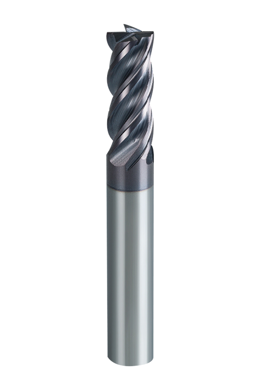
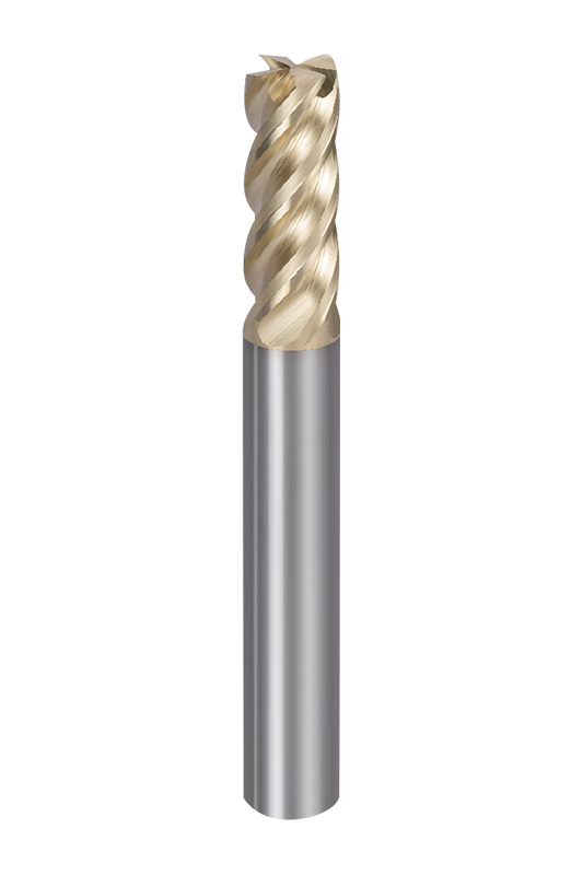
A bare carbide end mill will weld itself to stainless steel within seconds. Coatings act as a thermal barrier and friction modifier, enabling higher speeds and preventing chemical diffusion between chip and tool. But no single coating fits all applications.
| Coating | Color | Max Temp (°C) | Suitable Materials | Typical Application |
|---|---|---|---|---|
| TiN (Titanium Nitride) | Gold | 600 | General steels, cast iron, aluminum (with caution) | General purpose milling, reduced friction for gummy materials |
| TiAlN (Titanium Aluminum Nitride) | Violet‑black | 800 | Alloy steels, stainless steel, high‑temp alloys | Dry or MQL machining; excellent at high temperatures |
| AlTiN (Aluminum Titanium Nitride) | Dark grey | 900 | Hardened steels (≥50 HRC), titanium, nickel alloys | High‑speed finishing, hard milling, aerospace alloys |
| DLC (Diamond‑Like Carbon) | Black/grey | 400 (oxidation limit) | Aluminum, copper, graphite, composites | Abrasive non‑ferrous materials, electrode machining |
TiAlN outperforms TiN in stainless steel by forming a stable aluminum oxide layer at the cutting zone, which protects the carbide substrate up to 800°C. For hardened steel above 55 HRC, AlTiN’s higher aluminum content increases hot hardness. DLC, while limited in thermal stability, excels on graphite because its low friction prevents edge rounding and reduces dust adhesion. Choosing the coating demands matching operating temperature, workpiece reactivity, and chip abrasion simultaneously.
Operators often respond to sudden tool failure by simply slowing down, but the root cause determines whether that fix works or masks the problem until the next breakdown. Systematic diagnosis based on wear patterns saves tools and part quality.
A machine can run unattended, but tool life often collapses silently between shift changes. The practices below turn experience into repeatable results.
We are End Mills Manufacturer and End Mill Bits Factory. Our Footprints Are Around The World, We provide quality products and services to customers from all over the world.

No.233-3 Yangchenghu Road, Xixiashu Industrial Park, Xinbei District, Changzhou City, Jiangsu Province

+86-18068566610

sales@magotan-tools.com
+86-18068566610
