
Address:
No.233-3 Yangchenghu Road, Xixiashu Industrial Park, Xinbei District, Changzhou City, Jiangsu Province


Content
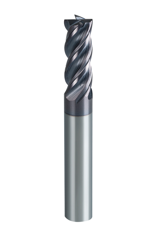
You’ve just mounted a fresh 1/4" end mill bit in your CNC router, ready to profile aluminum brackets. Within two minutes, the edges are ragged and the tool is screaming. The cause isn’t bad carbide; it’s a mismatch between the tool and the material. A 1/4" end mill—0.250 inches in cutting diameter—sits at the intersection of rigidity and chip clearance that makes it the default choice for CNC routers and light milling machines.
Its cross-section is stiff enough to tolerate side loads in profiling and slotting, yet large enough to keep flutes from packing with chips in deep pockets. That’s why job shops and hobbyists alike stock more 1/4" bits than any other diameter. Common tasks include:
In short, if you only keep one size in your tool drawer, it should be 1/4". But the right geometry and coating make the difference between a smooth part and a scrapped one.
Catalog pages list numbers that can mislead you. A 1/4" end mill is not just a cylinder with flutes—the flute count, coating, and corner style determine where it thrives and where it fails. Understanding these specs prevents you from buying a tool that looks right but performs wrong.
Flute count controls chip evacuation and core strength. A tool with fewer flutes has larger gullets for chip flow; one with more flutes has a thicker core and resists deflection better. The trade-off is critical when cutting deep slots or soft, gummy materials.
| Feature | 2-Flute | 4-Flute |
|---|---|---|
| Chip evacuation | Excellent — wide gullets clear chips quickly | Limited — prone to packing in deep slots |
| Rigidity / deflection | Lower — thinner core, more flex | Higher — thicker web, less chatter |
| Surface finish | Good for roughing; finish depends on feed | Better finish at higher feed rates |
| Best for | Slotting, aluminum, wood, plastics | Profiling, steel, hard metals, finishing |
| Chip thinning benefit | Moderate — fewer flutes need more rpm to match feed | Greater — allows higher feed per revolution |
Rule of thumb: choose 2 flutes when chip clearance dominates (deep slots in aluminum) and 4 flutes when rigidity and feed rate are priorities (steel profiling).
Coatings are not a performance band-aid; they are a deliberate match to the workpiece material. The wrong coating can accelerate wear by promoting built-up edge or overheating. The table below compares common options.
| Coating | Hardness (HV) | Max Work Temp (°C) | Friction Coeff. | Best For |
|---|---|---|---|---|
| Uncoated | — | — | 0.4 – 0.6 | Soft non-ferrous metals, wood, plastics; sharp edge |
| TiAlN | 3,300 – 3,500 | 800 | 0.3 – 0.4 | Steel, stainless, high-temp alloys; dry or MQL |
| AlTiN | 3,500 – 3,800 | 900 | 0.3 – 0.4 | Titanium, Inconel, hardened steels; extreme heat |
| ZrN | 2,800 – 3,000 | 550 | 0.2 – 0.3 | Aluminum, brass, copper; prevents built-up edge |
| DLC | 5,000 – 7,000 | 400 | 0.05 – 0.1 | Graphite, composites, non-ferrous; ultra-low friction |
For a typical shop cutting 6061 aluminum, an uncoated or ZrN-coated 2-flute tool will outperform a TiAlN-coated 4-flute every time. Match the coating to the thermal and chemical demands of the workpiece.
Beyond flutes and coating, three numbers demand attention. The shank diameter should match your collet or tool holder—most 1/4" end mills have a 1/4" shank, but some smaller mills use a 1/8" shank. The length of cut (LOC) determines maximum slot depth—never bury the tool deeper than 70% of LOC. Overall length (OAL) plus tool holder gauge length sets stick-out. And corner geometry: a square corner gives a sharp 90° floor, while a corner radius (often 0.010"–0.030") strengthens the edge and extends tool life in heavy roughing. If your design permits a small radius, use it.
Material dictates geometry. The same 1/4" end mill that sails through aluminum will gall and break in titanium. This decision matrix distills material requirements into a clear set of starting recommendations.
| Material | Flutes | Coating | Corner Style | Notes |
|---|---|---|---|---|
| Wood, MDF, plastics | 2 | Uncoated or low-friction | Square | High RPM; sharp edge prevents burning |
| Aluminum 6061 | 2 | Uncoated or ZrN | Square or slight radius | Wide gullets prevent chip packing; general-purpose carbide end mills work well for light profiling |
| Carbon steel 1018 | 4 | TiAlN | 0.015"–0.030" radius | Prefer chip thinning and moderate speeds; use coolant |
| Stainless steel 304 | 4 | TiAlN or AlTiN | Slight radius | Work hardening risk; keep feed high and speed moderate |
| Titanium Ti-6Al-4V | 4–5 | AlTiN | 0.020"–0.060" radius | Requires rigid setup and specialty tools; dedicated titanium end mills with variable helix control chatter |
| Graphite | 2 | Diamond-coated or DLC | Square | Abrasive dust demands sharp edges and wear-resistant coating |
These are starting points. Adjust based on machine rigidity and available spindle speed. For example, on a less rigid CNC router cutting aluminum, a 1/4" single-flute O-flute end mill sometimes outperforms a 2-flute because it provides better chip evacuation at high RPMs.
Guessing at RPM and feed damages tools and parts. The starting values below are calculated for a 1/4" solid carbide tool in a rigid setup with adequate coolant or mist. Use them as baselines and tune from there.
| Material | SFM | RPM | Chip Load (IPT) | Feed (IPM) 2-flute | Feed (IPM) 4-flute |
|---|---|---|---|---|---|
| Wood / MDF | 1,000 – 2,000 | 15,000 – 24,000 | 0.005 – 0.010 | 150 – 480 | 300 – 960 |
| Aluminum 6061 | 800 – 1,200 | 12,200 – 18,300 | 0.002 – 0.004 | 50 – 150 | 100 – 300 |
| Mild steel 1018 | 300 – 500 | 4,580 – 7,640 | 0.001 – 0.002 | 9 – 30 | 18 – 61 |
| Stainless 304 | 150 – 300 | 2,290 – 4,580 | 0.0005 – 0.0015 | 2 – 14 | 5 – 27 |
| Titanium Ti-6-4 | 100 – 180 | 1,530 – 2,750 | 0.0005 – 0.001 | 1.5 – 5.5 | 3 – 11 |
RPM formula: RPM = (SFM × 12) / (π × D). Example: For aluminum with SFM 800 and D = 0.25", RPM = (800 × 12) / (3.1416 × 0.25) = 12,222. Feed formula: IPM = RPM × CPT × number of flutes.
You are profiling the outside of a 0.5"-thick aluminum plate with a 1/4" 2-flute uncoated end mill. Starting SFM: 1,000. RPM = (1,000 × 12) / (π × 0.25) = 15,279. Choose a mid-range chip load of 0.003 IPT. Feed = 15,279 × 0.003 × 2 = 91.7 IPM. For a 0.25" radial engagement (full slotting would be 0.25" but profiling often uses 40–60% radial engagement), set radial depth to 0.100" and axial depth to 0.125". If the machine lacks rigidity, drop SFM to 800 and chip load to 0.002, yielding RPM 12,222 and feed 48.9 IPM—still a productive cut. Listen for chatter; if the tool squeals, reduce radial engagement first.
Even the best 1/4" end mill will fail prematurely if the setup fights it. These six practices shield the cutting edges from unnecessary stress.
A broken 1/4" end mill is a message. Reading the failure pattern reveals whether the problem is speed, feed, clamping, or tool selection. Use the table below to diagnose and correct the root cause before scrapping another part.
| Failure Mode | Likely Cause | Solution |
|---|---|---|
| Small chips along cutting edge (chipping) | Feed rate too high, material hard spots, or excessive run-out | Reduce feed; check tool run-out; examine workpiece for inclusions |
| Uniform flank wear band | Speed too high for material and coating | Lower SFM by 15–20%; verify coating is appropriate for material |
| Built-up edge (material stuck to flute) | Insufficient cutting temperature or adhesive material | Increase speed and feed slightly; switch to ZrN or DLC coating for aluminum |
| Thermal cracks perpendicular to edge | Rapid temperature changes from intermittent coolant or high-speed dry cutting | Use continuous flood coolant or completely dry; select AlTiN coating for hot cuts |
| Rapid corner wear | Abrasive material attacking the sharp corner | Switch to a corner radius end mill; reduce axial depth |
When a tool fails with no obvious pattern, suspect the setup. A loose collet, worn spindle bearings, or an unbalanced toolholder can mimic all these failure modes. Rule out mechanical issues before chasing parameters.
General-purpose end mills cover 80% of jobs, but a handful of materials punish standard geometry so severely that dedicated designs pay for themselves quickly—often in the first production run.
For stainless steel, work hardening can ruin a sharp edge within minutes. A variable-helix or unequal-tooth-pitch design breaks up harmonics and drastically reduces chatter. End mills built specifically for stainless steel with a high-helix (40°+) and TiAlN coating let you push feed rates without dulling the edge.
Titanium alloys demand AlTiN coatings and often a 5-flute design to balance chip load with core strength. The tools linked earlier for titanium (see the material matrix) exemplify this specialization, with optimized flute spacing and corner geometry that resist the high cutting temperatures of Ti-6Al-4V.
Graphite and abrasive composites eat standard carbide quickly. Diamond-coated tools, while more expensive, can run 10–20× longer in electrode machining. If your work regularly involves graphite, the cost per part drops sharply when you move to diamond.
Deciding when to switch from general-purpose to application-specific is about volume and tolerance. If scrapped parts and frequent tool changes erode your margin, the right specialty 1/4" end mill is not an upgrade—it’s a requirement.
We are End Mills Manufacturer and End Mill Bits Factory. Our Footprints Are Around The World, We provide quality products and services to customers from all over the world.

No.233-3 Yangchenghu Road, Xixiashu Industrial Park, Xinbei District, Changzhou City, Jiangsu Province

+86-18068566610

sales@magotan-tools.com
+86-18068566610
