


 English
 한국어
 русский

Address:
No.233-3 Yangchenghu Road, Xixiashu Industrial Park, Xinbei District, Changzhou City, Jiangsu Province


Content
Ask ten machinists how they picked a feed rate and you will get ten different answers, but the honest ones usually come back to the same small piece of arithmetic. The chip load formula ties spindle speed, feed rate and flute count together in a single line, and it is the quickest way to move from a gut feeling to a number you can actually defend at the machine. What follows is the formula itself, the unit conversions that trip people up, the chip-thinning correction that catches almost everyone, and the checks we run before trusting a new cutter on a production job.
Chip load, written as fz and often called feed per tooth, is the thickness of material that one cutting edge removes during a single revolution of the tool. It is a per-tooth figure, not a per-revolution figure, which is where a lot of confusion starts. A four-flute cutter turning at 8,000 rpm removes four chips per revolution, so the feed rate has to be shared out four ways.
That distinction matters because the chip is what carries heat away from the cutting zone. Push too light a chip and the edge rubs instead of cuts, generating heat in the workpiece and work-hardening stainless or titanium in the process. Push too heavy a chip and the edge simply runs out of strength, especially on small diameters. Chip load is the dial that sits between those two failures, and the formula is how you find it.
The core relationship is short enough to memorise:
fz = F ÷ (n × z)
where fz is chip load per tooth, F is the feed rate, n is spindle speed in rpm, and z is the number of flutes. Rearranged, it gives you the feed rate to programme: F = fz × n × z. Spindle speed itself comes from cutting speed, with n = (1000 × Vc) ÷ (π × D) in metric or n = 3.82 × SFM ÷ D in imperial, where D is the tool diameter.
| Quantity | Imperial | Metric |
|---|---|---|
| Spindle speed (n) | rpm | rpm |
| Feed rate (F) | inches per minute (IPM) | millimetres per minute (mm/min) |
| Flute count (z) | number of cutting edges | number of cutting edges |
| Chip load (fz) | inch per tooth (IPT) | millimetre per tooth (mm/tooth) |
| Calculation | IPM ÷ (rpm × z) | mm/min ÷ (rpm × z) |
One practical note from the shop floor: write the units down next to every number before you reach for the calculator. Nearly every wrong feed rate we get asked about traces back to a metric value entered into an imperial field, or the other way round.
Take a 10 mm three-flute carbide end mill in 6061 aluminium, with a cutting speed of 300 m/min and a target chip load of 0.06 mm per tooth. Spindle speed first: (1000 × 300) ÷ (3.1416 × 10) comes to roughly 9,550 rpm. Then the feed rate: 9,550 × 3 × 0.06 ≈ 1,719 mm/min, which most people round to 1,700 mm/min.
The imperial version behaves identically. A 1/2 inch four-flute cutter at 3,000 rpm with a target of 0.002 inch per tooth gives 3,000 × 4 × 0.002 = 24 IPM. If the machine or the setup cannot survive that feed, do not quietly drop the feed and keep the rpm — drop the spindle speed with it so the chip load stays where you intended it to be.
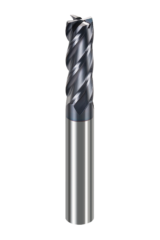 NNC Universal 4-Flute Flat Head End MillsNNC universal carbide four-flute flat end mills cover 1–20 mm, steel, stainless and cast iron; useful for aligning feed and spindle speed with chip load.View Product →
Everything above assumes the cutter is engaged across at least half its diameter. Drop below that, as you do in finishing passes, trochoidal toolpaths and deep pockets, and the chip physically cannot reach its nominal thickness because the arc of engagement is too short. The formula is still correct, but the number you programme needs correcting upwards.
The correction factor is CTF = 1 ÷ √(1 − (1 − 2 × ae ÷ D)²), where ae is the radial depth of cut and D is the tool diameter. At a radial engagement of 0.1 × D the factor works out at roughly 1.67, so a nominal 0.06 mm per tooth becomes about 0.10 mm per tooth in the program. Skip this step on a light finishing pass and you are effectively rubbing the edge along the wall, which is a common cause of poor surface finish and short tool life.
Charts are a starting point, not a verdict, but they save time when you have no history with a material. The ranges below are for a 6 mm carbide cutter in a reasonably rigid setup and should be scaled with diameter — a 1 mm tool runs a small fraction of these figures.
| Workpiece material | Typical chip load (mm/tooth) | What to watch |
|---|---|---|
| Aluminium alloys | 0.05 – 0.12 | Built-up edge if the chip is too light |
| Mild and low-carbon steel | 0.03 – 0.07 | Edge wear on long runs |
| Stainless steel | 0.02 – 0.05 | Work hardening and chatter |
| Titanium alloys | 0.02 – 0.04 | Heat concentration at the cutting edge |
| Hardened steel (45–55 HRC) | 0.01 – 0.03 | Tool deflection on small diameters |
| Graphite | 0.03 – 0.08 | Abrasive dust and edge rounding |
| Copper electrode stock | 0.02 – 0.06 | Burrs on fine ribs and thin walls |
Aluminium is where the formula really earns its keep, because the window between rubbing and overloading is wide and the payoff from running a proper chip is large. A three-flute wave-edge cutter designed for the material will happily take a heavy chip at high feed, and our aluminium feeds and speeds charts show how the numbers shift with alloy and diameter.
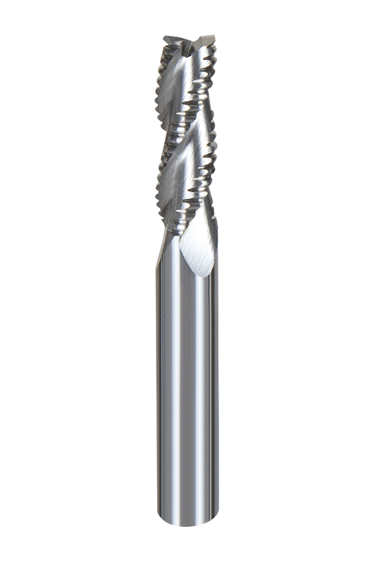 Custom 3-Flute Wave Edge End Mills for AluminiumThree-flute wave-edge carbide end mills for aluminium and silicon-aluminium alloys with models from 6 to 20 mm, designed for high metal removal and chip evacuation.View Product →
Titanium and other heat-resistant alloys punish an over-optimistic chip load faster than any other material we work with, because the heat has nowhere to go. The formula still applies, but the flutes, rake geometry and coating on the tool decide how much of the calculated figure you can actually use. A cutter built for titanium with the correct helix and edge preparation will hold a smaller chip load more consistently than a general-purpose tool pushed to the same number, and it will do so without the edge breaking down after forty minutes.
 Custom 4-Flute Flat End Mills for Titanium AlloyFour-flute carbide end mills for titanium with variable helix and unequal flute division, in 6–20 mm diameters, designed for anti-vibration roughing and high-speed machining.View Product →
Calculated numbers are a hypothesis; a test cut is the proof. Start at roughly 80 percent of the calculated feed and work upwards in 10 to 15 percent steps, listening for chatter and watching the chips rather than the spindle load alone. Thin, silvery chips that curl and break cleanly suggest you are near the sweet spot. Blue or powdery chips, a ringing sound, or a burnished wall mean the chip is too light or the setup is flexing.
The chip load formula is only three variables long, yet it explains most of what goes right or wrong at the spindle. Get the units straight, apply the chip-thinning correction when the radial engagement is light, and let a test cut confirm the arithmetic. If you are choosing between geometries for a particular material, our solid carbide end mill range is organised by workpiece material so you can match the tool to the job before the numbers are even entered.

We are End Mills Manufacturer and End Mill Bits Factory. Our Footprints Are Around The World, We provide quality products and services to customers from all over the world.


No.233-3 Yangchenghu Road, Xixiashu Industrial Park, Xinbei District, Changzhou City, Jiangsu Province


+86-18068566610


sales@magotan-tools.com
+86-18068566610
