


 English
 한국어
한국어
 русский

Address:
No.233-3 Yangchenghu Road, Xixiashu Industrial Park, Xinbei District, Changzhou City, Jiangsu Province


Content
Drilling is usually the first operation that teaches a machinist respect for cutting data. Feed a carbide drill too gently and it rubs, work-hardens the surface and dulls within a few holes. Push it too hard and the corners chip before the first hole is finished. The comfortable window between those two outcomes is narrower for carbide than for high-speed steel, and that is exactly why carbide drill speeds and feeds are worth a few minutes of thought before the spindle starts turning.
We grind solid carbide drills for a living, so the same questions reach us every week from job shops, mould makers and aerospace suppliers. The answers are not complicated. They simply need to be applied in the right order, and then adjusted with what the chips and the spindle tell you.
Speeds and feeds sound like one topic, but they are two separate decisions that solve two different problems.
Carbide tolerates roughly two to three times the surface speed of high-speed steel in the same material. What limits carbide is rarely softening of the edge. It is heat concentrated in a very small contact zone, plus the brittleness that makes a chipped corner fatal within seconds.
In imperial units, rpm = (SFM x 3.82) divided by the drill diameter in inches. In metric units, rpm = (Vc x 1000) divided by (3.14 x drill diameter in mm). A 10 mm carbide drill running at 80 m/min therefore needs 80 x 1000 divided by 31.4, which is about 2,546 rpm.
Feed rate in mm/min = rpm x feed per revolution. Staying with the same example, 2,546 rpm x 0.12 mm/rev gives roughly 306 mm/min. On a three-flute drill the same feed per revolution is shared across three cutting edges, so the load per edge is lower and hole quality usually improves in gummy materials.
If you would rather not run these numbers by hand for every tool in the crib, our drill speed and feed calculator with worked examples walks through the same formulas in both metric and imperial form.
The table below is the starting point we hand to customers who are moving from high-speed steel to solid carbide. It assumes a rigid setup, a drill with a length-to-diameter ratio of four or less, and coolant that reaches the cutting edge.
| Workpiece material | Surface speed (SFM) | Surface speed (m/min) | Feed per revolution (mm/rev) | Notes |
|---|---|---|---|---|
| Aluminium alloys | 300-600 | 90-180 | 0.10-0.30 | Polished flutes and strong chip evacuation |
| Mild and low-carbon steel | 200-350 | 60-105 | 0.08-0.20 | Watch for built-up edge on very soft grades |
| Alloy steel, 30-40 HRC | 150-250 | 45-75 | 0.08-0.15 | Rigidity matters more than coating choice |
| Austenitic stainless steel | 100-180 | 30-55 | 0.05-0.12 | Never dwell; keep the feed up to avoid work hardening |
| Grey cast iron | 250-400 | 75-120 | 0.10-0.25 | Often drilled dry with an air blast |
| Titanium alloys | 80-150 | 25-45 | 0.05-0.10 | Flood coolant, sharp edge, low surface speed |
| Hardened tool steel, 45-55 HRC | 60-120 | 18-36 | 0.03-0.08 | Use ultra-hard grades and short flute lengths |
Reduce surface speed by 20 to 30 percent for long-reach tools, thin-walled parts, or a machine with noticeable spindle runout. When a stainless steel job starts to squeal, resist the reflex to slow the feed down. A feed that is too light is the most common cause of work hardening, and work hardening is what destroys the next drill as well as the current one.
Check total indicated runout at the drill tip, not at the holder face. Keeping it under 0.02 mm roughly doubles the life of a small carbide drill, because an off-centre edge carries almost all the load on one corner. Shrink-fit and hydraulic holders are worth the money on diameters below 6 mm.
Through-spindle coolant reaches the tip where the heat is, so it supports the highest speeds in the table. Flood coolant works well for shallow holes in steel and stainless. Cast iron is often drilled dry with an air blast, while aluminium and titanium reward generous volume and pressure, since both materials move heat into the tool rather than the chip.
Chips are the cheapest feedback device on the machine, and they tell you which variable to change.
Cutting data only delivers results when the drill in the holder suits the job. Every tool we ship is ground and inspected on five- and six-axis machines at our factory in Changzhou, which is why we tend to talk about geometry before we talk about numbers.
A general-purpose solid carbide twist drill is the sensible default for carbon steel, alloy steel and cast iron across a wide diameter range.
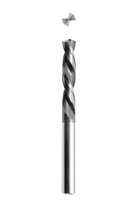 NNZT Series General Purpose Solid Carbide Twist DrillsA versatile default for carbon steel, alloy steel and cast iron, with external or internal cooling and diameters up to 25 mm.View Product →
For mild steel and stainless steel, a geometry with a reinforced web and a sharper rake keeps the edge alive and reduces built-up edge on softer grades.
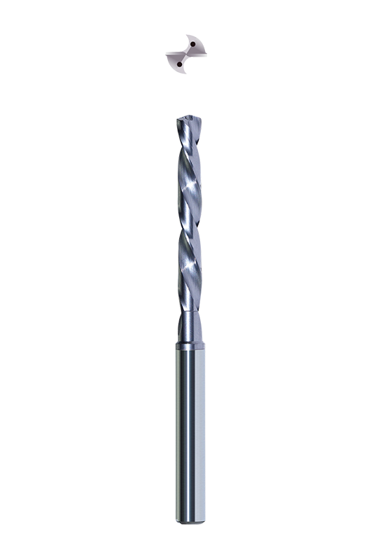 NNZB Series Solid Carbide Twist Drills for Mild Steel and Stainless SteelInternal-cooling 3D and 5D drills with sharp edges for mild and stainless steel, helping avoid built-up edge in diameters from 3 mm to 20 mm.View Product →
In cast iron and aluminium, a three-flute design clears chips faster and holds hole size better than a two-flute drill at the same feed per revolution.
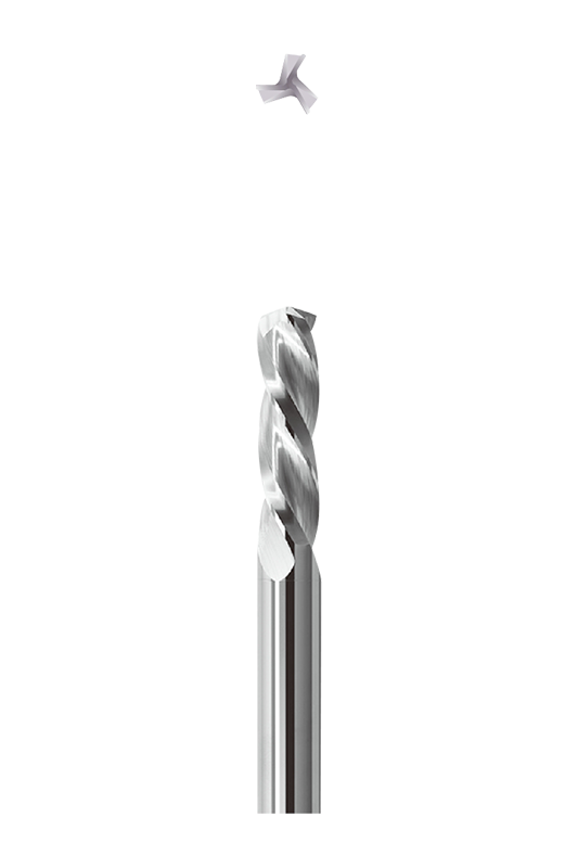 NNZL Series Solid Carbide Three-Flute Drills for Cast Iron and AluminumNon-coated three-edge drills in external-cooling 3D and internal-cooling 15D types, suited to cast iron, aluminum alloys and faster chip clearance.View Product →
Around 100 m/min is a safe starting point, which works out at roughly 5,300 rpm. Pair that with 0.10 to 0.15 mm/rev and a peck cycle once you pass about 18 mm of depth.
Squealing with corner chipping nearly always means surface speed is too high for the coating and the coolant supply. Drop the speed by 20 percent, confirm the coolant is hitting the tip, and check runout before assuming the tool is at fault.
On a flat surface with a solid carbide drill that has a 140-degree point, spotting is often unnecessary and simply adds a second operation. A spot is still useful on curved, angled or interrupted surfaces, or when a long drill needs help finding its position.
There is no single correct number for carbide drilling, only a sensible starting point and a short list of things to watch. Start conservative, listen to the machine, read the chips, and change one thing at a time. Do that consistently and the same drill will keep producing accurate holes long after a chart-only approach has burned through three of them.

We are End Mills Manufacturer and End Mill Bits Factory. Our Footprints Are Around The World, We provide quality products and services to customers from all over the world.


No.233-3 Yangchenghu Road, Xixiashu Industrial Park, Xinbei District, Changzhou City, Jiangsu Province


+86-18068566610


sales@magotan-tools.com
+86-18068566610
