


 English
 한국어
한국어
 русский

Address:
No.233-3 Yangchenghu Road, Xixiashu Industrial Park, Xinbei District, Changzhou City, Jiangsu Province


Content
Run a 12 mm solid carbide drill at 800 RPM into 304 stainless steel and the edges rub instead of cut: the surface work-hardens, heat pours into the tool, and the corners chip within a few holes. Run the same drill at roughly 1,590 RPM with a 0.15 mm/rev feed, and each edge takes a proper bite, heat leaves with the chips, and the tool can outlast hundreds of holes. That difference is exactly what a drill speed and feed calculator exists to resolve. It converts two inputs—surface speed and feed per revolution—into the spindle RPM and feed rate your machine control actually needs. The arithmetic takes seconds; the accuracy lives in the input values, and that is where most shops either win or waste money.
Every calculator, whether a phone app, a web tool, or a shop spreadsheet, solves the same two equations: RPM = (SFM × 3.82) / tool diameter in inches, and feed rate (IPM) = RPM × feed per revolution (IPR).
In metric units the first equation becomes RPM = (Vc × 1,000) / (π × D), with Vc in m/min and D in mm. Surface speed describes how fast the cutting edge travels through the workpiece; feed per revolution describes how far the drill advances in one full turn. Together they set chip thickness, heat generation, and cutting time, which the better calculators also report: hole depth plus a short approach allowance, divided by feed rate, gives cycle time per hole.
Drills are specified by feed per revolution because both flutes cut simultaneously. For a two-flute drill, feed per tooth is simply half of feed per revolution, so a 0.006 IPR feed puts roughly 0.003 in. of chip load on each edge. Dedicated drilling calculators take IPR directly, which removes a common error when shops reuse milling formulas built around feed-per-tooth inputs and flute counts. If your calculator insists on chip load per tooth, divide the IPR you intend to run by two before entering it.
A calculator is only as good as the SFM value you feed it. Catalog numbers for high-speed steel drills do not transfer to solid carbide: carbide sustains roughly two to three times the cutting speed, so an HSS-based entry will run a carbide tool far below its efficient range, producing stringy chips and longer cycle times than the tool was designed for. The ranges below are realistic starting points for coated solid carbide twist drills on rigid CNC machines with flood or through-tool coolant. They are deliberately conservative; tune from chip behavior, not from habit.
| Workpiece material | Starting surface speed | Feed per revolution (0.25–0.50 in. drills) |
|---|---|---|
| Aluminum alloys | 350–500 SFM (105–150 m/min) | 0.006–0.014 IPR (0.15–0.35 mm/rev) |
| Low-carbon steel | 250–350 SFM (75–105 m/min) | 0.004–0.010 IPR (0.10–0.25 mm/rev) |
| Alloy steel (4140, 300 HB) | 150–250 SFM (45–75 m/min) | 0.003–0.008 IPR (0.08–0.20 mm/rev) |
| Stainless steel (304/316) | 100–180 SFM (30–55 m/min) | 0.003–0.007 IPR (0.08–0.18 mm/rev) |
| Gray cast iron | 200–300 SFM (60–90 m/min) | 0.005–0.012 IPR (0.12–0.30 mm/rev) |
| Titanium (Ti-6Al-4V) | 80–150 SFM (25–45 m/min) | 0.002–0.006 IPR (0.05–0.15 mm/rev) |
Treat the feed column as a band rather than a target. Larger diameters sit toward the high end because the drill core is stiffer and the flutes carry more chip; small diameters belong at the low end. On a light-duty mill or a long, thin part, cut both numbers back by roughly a quarter and work upward.
Example 1: a 0.500 in. coated carbide drill in 6061-T6 aluminum. At 400 SFM, RPM = (400 × 3.82) / 0.500 ≈ 3,050 RPM. From the aluminum band, pick 0.010 IPR: feed = 3,050 × 0.010 ≈ 30 IPM. On a rigid machining center with flood coolant, a general-purpose solid carbide twist drill will run these numbers all shift long:
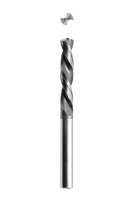 General Purpose Solid Carbide Twist Drill Bits• Suitable for efficient drilling of various materials such as steel, cast iron, stainless steel, etc. • Straight shank twist drill with internal/external cooling.View Product →
Example 2: a 12 mm carbide drill in 304 stainless. RPM = (60 × 1,000) / (π × 12) ≈ 1,590 RPM; feed = 1,590 × 0.15 ≈ 240 mm/min, about 9.4 IPM. Notice how much lower the cutting speed is than the aluminum case—roughly 60 m/min versus 120 m/min and up—while the feed per revolution stays firm. Stainless rewards confidence: a hesitant feed hardens the surface and kills edges.
Example 3: a 0.250 in. carbide drill in 4140 alloy steel at about 300 HB. At 220 SFM, RPM = (220 × 3.82) / 0.250 ≈ 3,360 RPM; at 0.004 IPR, feed ≈ 13 IPM. If the drill overhangs far from the spindle or the part is clamped in a tall vise, halve the feed first and restore it once the chips look right.
Every calculator assumes ideal conditions: rigid setup, coolant reaching the cutting edge, and hole depths below roughly four times the diameter. Real holes need manual corrections, and four of them come up constantly.
Past about 4×D, chip packing becomes the limiting factor rather than heat. Reduce feed by 20 to 30 percent, program retract moves to break the chip if the machine has no through-tool coolant, and for 8×D and beyond switch to a dedicated deep-hole geometry; its flute profile and point construction differ enough from a standard drill's that treating the two the same ruins both. When a pilot hole precedes the main drill, size it to clear the web, following the pilot hole sizing methods that also apply to carbide tool selection.
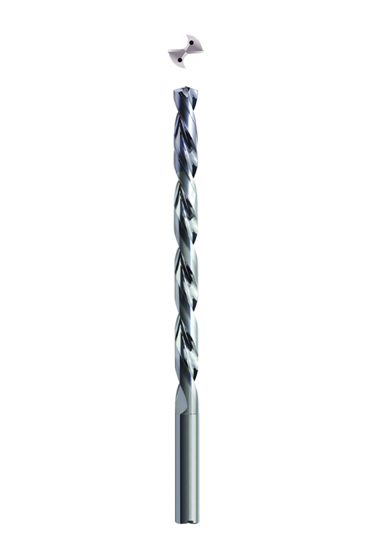 Deep Hole Drills Twist Drill Bits• Suitable for efficient drilling of various materials such as steel, cast iron, stainless steel, etc. • Straight shank twist drill with internal/external cooling.View Product →
The calculator does not know your point angle. A 135° split point self-centers and cuts with noticeably lower thrust, which helps you hold the calculated feed on less rigid machines; a conventional 118° point pushes harder and benefits from a spot-drilled start. Many carbide drills split the difference with a 140° point for stable, low-thrust entry. The trade-offs, including when each geometry protects a carbide edge, are broken down in this 118° vs. 135° drill point angle guide.
Austenitic grades such as 304 and 316 harden under light, rubbing cuts. Keep the calculated feed constant through the hole, never dwell at breakthrough, and avoid shallow peck retracts that re-enter a hardened layer. Geometry helps as much as the numbers: drills ground specifically for stainless carry polished flutes and a point that shears cleanly at these modest surface speeds:
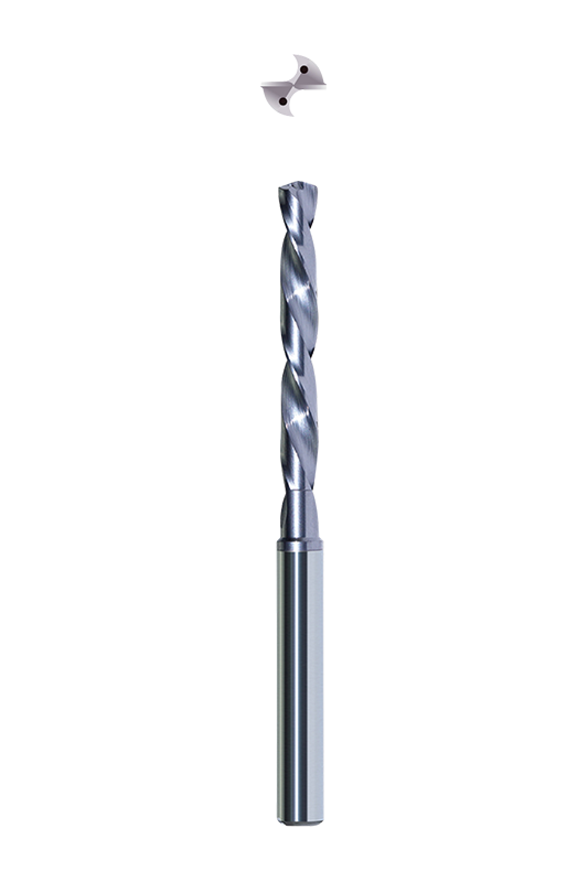 Twist Drills for Mild Steel and Stainless Steel• First choice for drilling soft steel and stainless steel. • Sharp cutting edge, avoids the formation of built-up edge, suitable for high-performance drilling. • Stra...View Product →
Calculator output is a starting point, not a specification. The cutting values we publish for our solid carbide drills are developed on the same multi-axis grinders that produce the tools, then verified in the materials our customers machine daily, from titanium structures to automotive aluminum, cast iron, and die and mold steels. When a job sits outside the ordinary—a deep bore in hardened stainless, a cluster of small-diameter holes in titanium—a short conversation with your tool supplier about L/D ratio, coolant delivery, and machine rigidity will save more time than any stretch of trial and error on the floor. Run the numbers first, then let the chips confirm them.

We are End Mills Manufacturer and End Mill Bits Factory. Our Footprints Are Around The World, We provide quality products and services to customers from all over the world.


No.233-3 Yangchenghu Road, Xixiashu Industrial Park, Xinbei District, Changzhou City, Jiangsu Province


+86-18068566610


sales@magotan-tools.com
+86-18068566610
