


 English
 한국어
한국어
 русский

Address:
No.233-3 Yangchenghu Road, Xixiashu Industrial Park, Xinbei District, Changzhou City, Jiangsu Province


Content
When you program a tapping cycle, the feed rate is not a free variable. Thread geometry fixes it: every spindle revolution must advance the tap by exactly one pitch. A 1/4-20 UNC tap must move 0.050 inch per revolution, and an M6x1.0 tap must move 1.0 mm. If the machine feeds at any other rate, the tap cuts the wrong lead, pushes the thread form, or breaks. That is why the practical question is never "what feed should I enter" but "what RPM should I run this fixed feed at."
The same relationship applies whether you use a floating tap holder or full rigid tapping: the spindle and the feed axis must stay synchronized so that the tap follows the pitch exactly. Once that is understood, the rest of tapping setup becomes a speed-selection problem, not a feed-selection problem. For a broader look at how internal and external threading fit together, our tapping and threading fundamentals article covers the full process.
Surface speed is the starting point, expressed in surface feet per minute (SFM). Convert it to spindle speed with the standard formula:
RPM = (SFM x 3.82) / tap diameter in inches
The 3.82 is simply 12 divided by pi, the unit conversion from feet and inches to revolutions. For a 1/4-20 tap in mild steel at a starting speed of 50 SFM, the calculation is (50 x 3.82) / 0.25 = 764 RPM.
Once RPM is set, the feed is dictated by the thread. For imperial threads, feed in inches per minute equals RPM divided by threads per inch: IPM = RPM / TPI. For the 1/4-20 example, that is 764 / 20 = 38.2 IPM.
For metric threads, feed in mm per minute equals RPM multiplied by the pitch: mm/min = RPM x pitch (mm). An M6x1.0 tap in stainless steel at 25 SFM gives RPM = (25 x 3.82) / 0.236 = 405 RPM, and feed = 405 mm/min.
These numbers look high compared with drilling feeds, which surprises many operators. The reason is that the tap cuts around the full circumference of the pre-drilled hole with several cutting edges, and the chip load per tooth is set by the pitch geometry. A long-standing shop rule for low-carbon steel is to start at roughly ten times the threads per inch, which fixes the feed at about 10 IPM. It is conservative, taps almost any mild steel safely, and still helps on older machines without rigid tapping.
The table below gives practical starting SFM values for cut taps and form taps. They are intentionally conservative; production shops adjust upward after confirming chip flow and thread finish on the first few holes.
| Workpiece material | HSS cut tap SFM | Coated HSS tap SFM | Form tap SFM |
|---|---|---|---|
| Aluminum and aluminum alloys | 60–90 | 90–120 | 80–110 |
| Low-carbon and mild steel | 40–60 | 60–80 | 50–70 |
| Alloy and tool steel | 30–40 | 40–55 | 35–45 |
| Stainless steel (300 series) | 20–30 | 30–40 | 25–35 |
| Gray cast iron | 50–70 | 70–90 | Not recommended |
| Titanium alloys | 15–25 | 20–30 | Not recommended |
The percentage of thread engagement is the largest lever on tapping torque. A standard tapped hole at 75 percent engagement cuts a larger chip area than a 65 percent thread, and the torque difference is roughly 15 to 20 percent. For weak threads in aluminum or for small taps below M4, dropping engagement to 60 to 65 percent is a common way to reduce tap breakage. The trade-off is lower thread strength on thin-walled parts, so the design engineer should approve the reduced engagement before you change the drill size.
Spiral-point (gun) taps push chips forward and are ideal for through holes. Spiral-flute taps pull chips back out of blind holes, but the flute geometry adds friction, so blind-hole tapping usually runs 10 to 20 percent slower than the same size through-hole cycle. Forming taps displace material instead of cutting it and can run 1.5 to 2 times faster than cut taps, provided the hole size is correct for forming and the lubrication is a high-pressure oil or a dedicated water-soluble fluid.
Coatings change the picture as well. A TiN or TiCN coating on an HSS tap reduces edge friction and permits 20 to 30 percent higher speed in steel, but the limiting factor remains lubrication: without effective coolant delivery, the coating prevents welding but does not solve chip evacuation. Rigid tapping also depends on a synchronous spindle; a floating holder adds a little safety margin but limits the usable speed. Always verify that the holder style matches what you are asking the tap to do.
There are three situations where the tap speed table no longer helps: large diameters, hardened materials, and deep blind holes with long chips. A 1-inch tap at 40 SFM runs below 200 RPM, and the tap still has to generate full torque to cut the complete thread circumference; breakage risk is high, and a broken tap in a large hole is expensive to remove. In hardened steel above roughly 45 HRC, a tap fights both the material hardness and the chip load around its full circumference. For such cases, we build and recommend the RX metric superhard two-row thread milling cutter for 65 HRC, because thread milling removes that full-circumference engagement and controls chip load flute by flute.
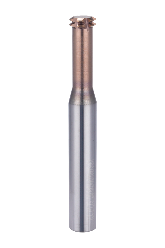 RX Metric Superhard Two-Row Thread Milling Cutter (Suitable for ≤65HRC) SupplierMaton Tools is China RX Metric Superhard Two-Row Thread Milling Cutter (Suitable for ≤65HRC) Suppliers and Factory, Custom RX Metric Supe...View Product →
When a job moves from tapping to thread milling, the speed and feed logic changes completely. Feed is no longer dictated by pitch; it is set from cutter diameter, flute count, and chip load per tooth. That gives the programmer the same freedom as with an end mill. A detailed thread milling vs. tapping comparison shows where each method wins on cost, tool life, and thread quality.
For a thread milling cutter, calculate RPM using the cutter diameter exactly as you would for an end mill: RPM = (SFM x 3.82) / cutter diameter. Then set feed per tooth from the manufacturer's recommendation and multiply by tooth count: feed (IPM) = RPM x teeth x chip load per tooth. The pitch only affects the helical interpolation path, not the feed rate. Our thread milling cutter speeds and feeds guide is the reference we use when quoting data for our own tools, and it applies the same way to metric, UN, and pipe thread forms.
A single-tooth thread mill is the most flexible option in the shop: one cutter body produces a wide range of diameters and pitches because the tooth generates the thread along a helical path. That is useful for prototype work and for families of similar threads. Our 60-degree metric single-tooth thread milling cutter is the tool we reach for when a customer needs short runs across several thread sizes without buying a dedicated tap for each one.
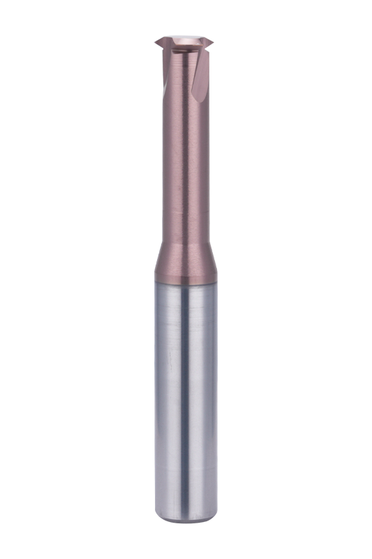 60°Metric Single Tooth Thread Milling Cutter Suppliers, Factory - Changzhou MatoMaton Tools is China 60°Metric Single Tooth Thread Milling Cutter Suppliers and Factory, Custom 60°Metric Single Tooth Thread Milling Cut...View Product →
Thread mills can also remove a process step. A multifunction cutter plunges at hole center and mills the full thread profile without a pre-drilled pilot hole, which saves a spotting or center-drilling operation and shortens cycle time. The multifunction thread milling cutter without pilot hole for steel machining works that way and is a direct answer to the question "can I thread faster by removing operations."
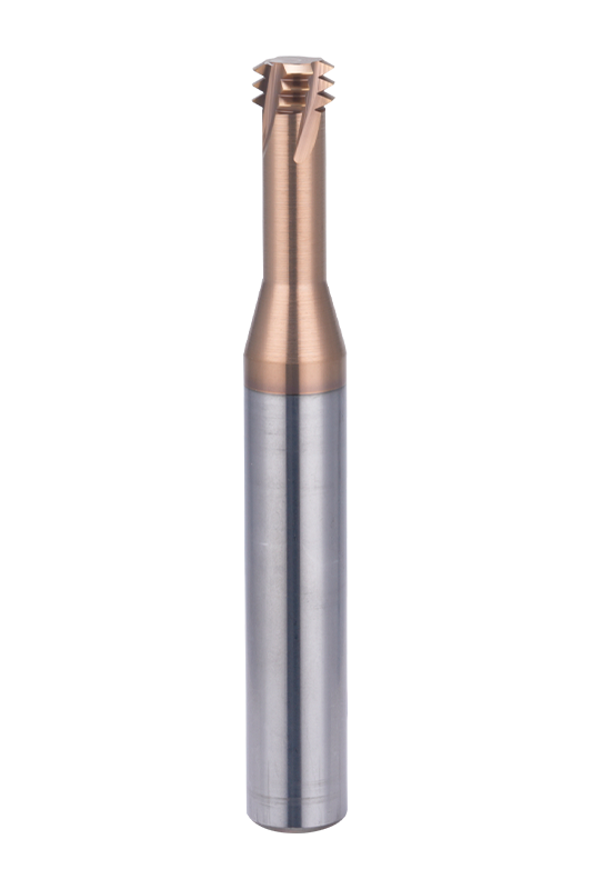 Multi-Function Thread Milling Cutter Without Pilot Hole For Steel Machining SuppMaton Tools is China Multi-Function Thread Milling Cutter Without Pilot Hole For Steel Machining Suppliers and Factory, Custom Multi-Func...View Product →
The fixed relationship between feed and pitch makes tapping straightforward to set up once you respect it. When the speed table stops covering the job, thread milling gives you back the control, and it is often the better production answer.

We are End Mills Manufacturer and End Mill Bits Factory. Our Footprints Are Around The World, We provide quality products and services to customers from all over the world.


No.233-3 Yangchenghu Road, Xixiashu Industrial Park, Xinbei District, Changzhou City, Jiangsu Province


+86-18068566610


sales@magotan-tools.com
+86-18068566610
